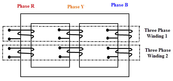
Construction of Three Phase Transformers

A three-phase transformer can be constructed by using common magnetic core for both primary and secondary winding. As we discussed in the case of single phase transformers, construction can be core type or shell type. So, for a bank of three phase core type transformer, three core type single phase transformers are combined. Similarly, a bank of three phase shell type transformer is get by properly combining three shell type single phase transformers. In a shell type transformer, EI laminated core surrounds the coils whereas in core type coil surrounds the core.
In core type three phase transformer, core is made up of three limbs or legs and two yokes. The magnetic path is formed between these yokes and limbs. On each limb both primary and secondary winding are wounded concentrically. Circular cylindrical coils are used as the winding for this type of transformer. The primary and secondary winding of one phase are wounded on one leg. Under balanced condition, the magnetic flux in each phase of the leg adds up to zero. Therefore, under normal conditions, no return leg is needed. But in case of unbalanced loads, high circulating current flows and hence it may be best to use three single phase transformers.

Fig:Core Type Construction
Shell Type Construction.
In shell type, three phases are more independent because each phase has independent magnetic circuit compared with core type transformer. The construction is similar to the single-phase shell type transformer built on top of another. The magnetic circuits of this type of transformer are in parallel. Due to this, the saturation effects in common magnetic paths are neglected. However, shell type constructed transformers are rarely used in practice.

Fig: Shell Type
Working of Three Phase Transformers.
Consider the below figure in which the primary of the transformer is connected in star fashion on the cores. For simplicity, only primary winding is shown in the figure which is connected across the three phase AC supply. The three cores are arranged at an angle of 120 degrees to each other. The empty leg of each core is combined in such that they form center leg as shown in figure.

Fig: working of a transformer
When the primary is excited with the three-phase supply source, the currents IR, IY and IB are starts flowing through individual phase winding. These currents produce the magnetic fluxes ΦR, ΦY and ΦB in the respective cores. Since the center leg is common for all the cores, the sum of all three fluxes are carried by it. In three phase system, at any instant the vector sum of all the currents is zero. In turn, at the instant the sum of all the fluxes is same. Hence, the center leg doesn’t carry any flux at any instant. So even if the center leg is removed it makes no difference in other conditions of the transformer.
Likewise, in three phase systems where any two conductors act as return for the current in third conductor, any two legs acts as a return path of the flux for the third leg if the center leg is removed in case of three phase transformer. Therefore, while designing the three-phase transformer, this principle is used.
These fluxes induce the secondary EMF in respective phase such that they maintain their phase angle between them. These EMF drives the currents in the secondary and hence to the load. Depends on the type of connection used and number of turns on each phase, the voltage induced will be varied for obtaining step-up or step-down of voltages.
No comments:
Post a Comment